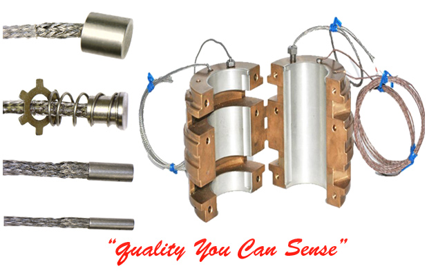
4 Wire RTD Bearing Sensor
Serious lead-wire resistance errors can occur when using a two-wire RTD (see Fig. 3A), especially in a 100Ω sensor. In a two-wire circuit, a current is passed through the sensor. As the temperature of the sensor increases, the resistance increases. This increase in resistance will be detected by an increase in the voltage (V = I•R). The actual resistance causing the voltage increase is the total resistance of the sensor and the resistance introduced by the lead wires. As long as the lead wire resistance remains constant, it can be offset and not affect the temperature measurement. The wire resistance will change with temperature, however, so as the ambient conditions change, the wire resistance will also change, introducing errors. If the wire is very long, this source of error could be significant. Two-wire RTDs are typically used only with very short lead wires, or with a 1000Ω element.
 |
In a 3-wire RTD(see Fig. 3B), there are three leads coming from the RTD instead of two. L1 and L3 carry the measuring current, while L2 acts only as a potential lead. Ideally, the resistances of L1 and L3 are perfectly matched and therefore canceled. The resistance in R3 is equal to the resistance of the sensor Rt at a given temperature—usually the begining of the temperature range. At this point, V out = zero. As the temperature of the sensor increases, the resistance of the sensor increases, causing the resistance to be out of balance and indicated at V out. Resistances L1 and L3 in leads up to tens of feet long usually match well enough for 100 ohm three-wire RTDs. The worst case is resistance offset equal to 10% of single-lead resistance.
The optimum form of connection for RTDs is a four-wire circuit (see Fig. 3C). It removes the error caused by mismatched resistance of the lead wires. A constant current is passed through L1 and L4; L2 and L3 measure the voltage drop across the RTD. With a constant current, the voltage is strictly a function of the resistance and a true measurement is achieved. This design is slightly more expensive than two or three-wire configurations, but is the best choice when a high degree of accuracy is required.
|