Bearing RTD Sensors
Bearing RTD Sensor Overview
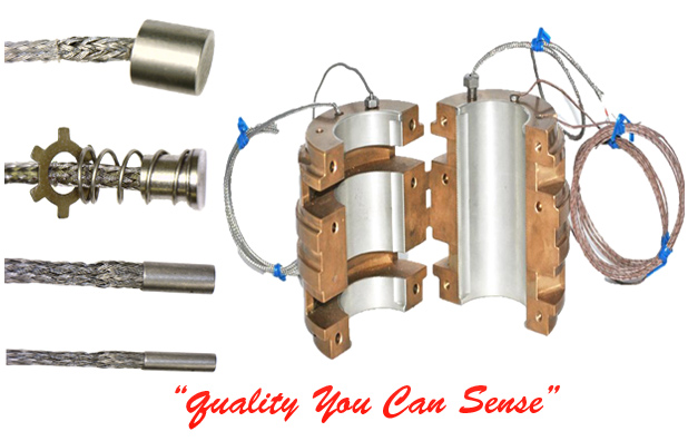
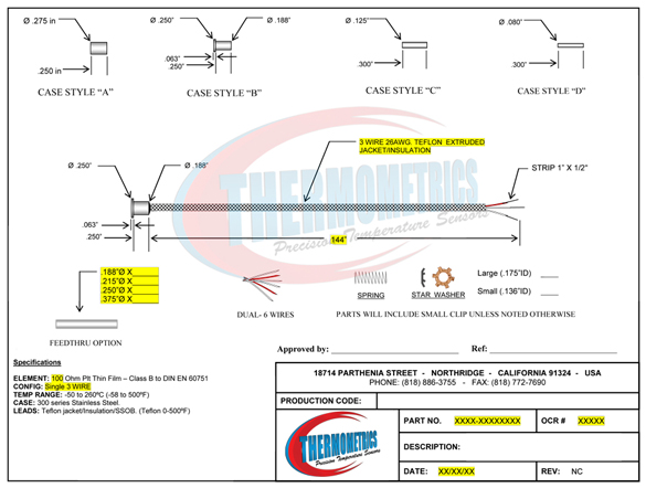
Bearing RTDs are designed for areas where there are space limitations. They are small, compact and are often used to detect temperature increases in bearings, thrust bearing plates, shafts and motor windings. They are miniature low mass sensors which are fast responding. Bearing sensors are manufactured using thin film technology and by design are tip sensitive and vibration resistant. They can be spring loaded into a bearing housing or held in position with a high temperature epoxy resin.
Bearing RTD Applications
•Motor Windings
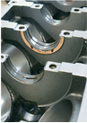
•Bearings
•Shafts
•Thrust Plates
•Applications where there is a space limitation
Bearing RTD Attributes
•Tip sensitive thin film technology
•Fast responding to sudden temperature changes
•Minature design. Sizes from 0.125 Inches in diameter and 0.30 in length.
•Designed for temperatures to -50 to 260°C (-58 to 500°F)
•Teflon single or double insulated lead wire.
•Optional wear resistant stainless steel braided jacket
•Available with spring loaded mounting and retaining thrust washer
•A variety of tip dimensions available to suit a particular application.
•Vibration proof solid design with no moving parts.
•Element encapsulation using high temperature epoxy resin.
•Moisture proof design. Oil Resistant Design
Bearing RTD Specifications
•Sensor Element: Platinum 100Ω ±0.12% at 0°C
•Measuring Range: -50 to 260°C (-58 to 500°F)
•Case Material: Tin plated copper alloy and Stainless Steel
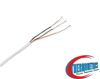
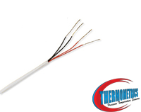
•Wiring Configuration: 2, 3, and 4 wire (single) 2 or 3 wire (dual)
•Accuracy Range: Class B to DIN EN 60751 Class A to DIN EN 60751
•Tip Construction: Tip sensitive
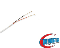
•Termination: Stranded copper with PTFE insulation; stainless steeloverbraid optional (one sleeve covers all leads).
•Time Constant: 3.0 seconds(case style A) to 1.5 seconds(case style D), typical value in moving water.
•Insulation Resistance: 10 megohms min. at 100 VDC, leads to case.
•Options: Calibration- singlepoint or multiple points
General RTD Overview
Are temperature sensors that contain a sensing element whose resistance changes with temperature. These sensors are often placed so they can be in a position in the process where it can reach the same temperature. Platinum wire or films RTDs are the most common type in use today. Platinum RTDs are used to measure temperatures from -400 °F to 1550 °F. Due to higher accuracy and repeatability RTDs are slowly replacing the use of thermocouples in many industrial applications below 1200°F.
Two-Wire RTD:
Provides one connection to each end of the element. This construction is suitable where the resistance of the lead wire may be considered as an additive constant in the circuit, and particularly where the changes in lead resistance due to ambient temperature changes may be ignored.
Three-Wire RTD:
Provides one connection to one end of the element and two to the other end of the element. Connected to an instrument designed to accept three-wire input, sufficient compensation is usually achieved for leadwire resistance and temperature change in Leadwire resistance. This is the most commonly used configuration.
Four-Wire RTD:
Provides two connections to each end of the element to completely compensate for leadwire resistance and temperature change in lead wire resistance. This configuration is used where highly accurate temperature measurement is vital.
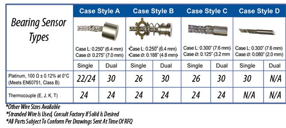
BEARING RTD SENSOR SPECIFICS
FEATURES
• For embedded applications in rotating machines
• RTDs – 100Ω platinum, 0.00385 Ω/Ω/°C
• Various styles and sizes
• Operating Temperature: to +250° F (+120° C)
• Thermocouple assemblies also available – consult factory
SPECIFICATIONS
RTDs: 100Ω platinum, 0.00385 Ω/Ω/°C; 2-, 3- and 4-wire single element configurations, Class 'B' tolerance to DIN 43760:1980 and IEC 751:1995 Silver plated, stranded copper conductors, 24 AWG, Teflon® insulated with extruded Teflon jacket overall or 24 or 26 AWG, Teflon insulated with optional stainless steel braid and extruded Teflon jacket overall.
Sheath Materials: 316SST, Copper Alloy or Brass.
Resistance Temperature Detectors also known as RTDs, accurately sense temperature with an excellent degree of repeatability and interchangeability of elements. RTD stands for Resistance Temperature Detector. RTDs are sometimes referred to generally as resistance thermometers. The RTD is composed of certain metallic elements whose change in resistance is a function of temperature. In operation, a small excitation current is passed across the element, and the voltage, which is proportional to resistance, is then measured and converted to units of temperature calibration. The RTD element is manufactured by winding a wire (wire wound elements) or plating a film (thin film elements) on a ceramic or glass core and sealing the element within a ceramic or glass capsule.
Since the majority of RTDs have low initial resistance, often 100 ohms, and have a small change in resistance per unit of temperature range, the resistance of the lead wire is often compensated for with a three or four wire bridge configuration built into the measuring devices. By selecting the proper elements and protective sheathing, RTDs can operate in a temperature range of (-200 to 650) C [-328 to 1202] F.
Thermometrics manufactures RTDs for a variety of industry applications. From single- or dual-element RTDs, to PT100's to Sanitary CIP types, Thermometrics has the right sensor for your job. If what you need is not available from our company catalog, our product engineers and sales staff will design an RTD for your specific application, including temperature sensor assemblies that require connection heads, thermowells and/or transmitters.
RTD INSTALLATION & MAINTENANCE
General
An RTD is a sensor whose resistance changes as its temperature changes. The resistance increases as the temperature of the sensor increases. The resistance vs temperature relationship is well known and is repeatable over time. An RTD is a passive device. It does not produce an output on its own. External electronic devices are used to measure the resistance of the sensor by passing a small electrical current through the sensor to generate a voltage.
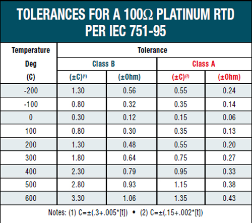
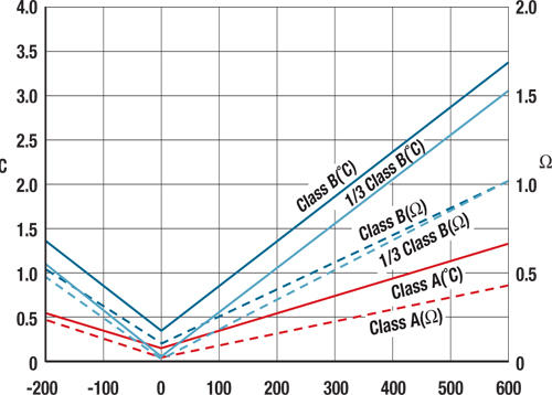
Standard Tolerances
RTDs are built to several standardized curves and tolerances. The most common standardized curve is the ‘DIN’ curve. The curve describes the resistance vs. temperature characteristics of a Platinum, 100 ohm sensor, the standardized tolerances, and the measurable temperature range. The DIN standard specifies a base resistance of 100 ohms at 0?C, and a temperature coefficient of .0038500 ohms/ohms/?C. The nominal output of a DIN RTD sensor is shown below:
There are two standard tolerance classes for DIN RTDs. These tolerances are defined as follows:
DIN Class A
Temperature tolerances:
+/-(0.15 + .002|T|°C)
DIN Class B
Temperature tolerances:
+/-(0.3 + .005|T|°C)
DIN Class C
Temperature tolerances:
+/-(1.2 + .005|T|°C)
Temperature Sensor Connections
RTD Sensors are available in a number of different leadwire configurations. The most common configuration is the single element, three lead configuration. Schematics of the available leadwire configurations are shown below:
Two wire sensors are typically used in applications where accuracy is not critical. The two wire configuration allows for the simplest measurement technique, but suffers from an inherent inaccuracy due to the resistance of the sensor leads. In the two wire configuration, there is no way to directly compensate for the resistance of the leadwires which will cause an offset increase in the resistance measurement.
Three wire sensors are built with a compensation loop to allow the measurement to factor out the resistance of the leads. With this configuration, the controller/measurement device makes two measurements. The first measurement measures the total resistance of the sensor and the connecting leadwires. The second measurement is the resistance of the compensation loop resistance. By subtracting the compensation loop resistance from the total resistance, an account net resistance is determined. Three wire sensors are the most common and give a good combination of accuracy and convenience.
The four wire sensor configuration and measurement techniques allow measurement of the sensor resistance without the influence of the leadwires. While this technique gives the best accuracy, many industrial controllers/measurement devices cannot make a true four wire measurement.
The transition from the sensor leadwires to the field wiring is typically done in a connection head attached to the sensor. Terminal blocks are used to facilitate the connection. A typical terminal block/sensor connection is shown in the following figure.
RTD Pages:
100ohm RTD Bearing Sensor
1000ohm RTD Bearing Sensor
2 Wire RTD Bearing Sensor
3 Wire RTD Bearing Sensor
4 Wire RTD Bearing Sensor
RTD Description
About RTD Temperature Probes
Introduction to RTDs
PT100 Bearing Sensor
Copper Tip Bearing Sensor
Dual Bearing Sensor
|