Temperature Drift
When a thermocouple is used to measure the temperature of an environment, it is expected that the acquired voltage does not change if the temperature of the environment is constant. In reality the voltage can change with time, even though the temperature of the environment is constant: this phenomenon is called drift and is a source of error in thermocouple measurement.
Drift occurs because of metallurgical changes of the thermoelements during the operation of the thermocouple: as these changes are time dependent, the change in voltage from the expected value (drift) is time dependent. An example of drift is shown in figure 10 for a 1.5mm diameter bare wire type K thermocouple exposed at 500°C: the change in voltage in microvolts is reported as a function of the exposure time.
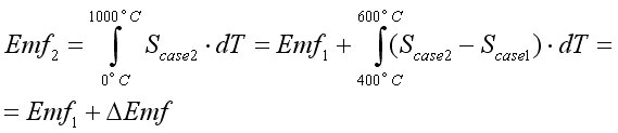
In order to understand better drift, let us consider the following example: let us assume that the thermocouple before exposure (case1, figure 11) has a constant Seebeck coefficient of 30μV/K and that the junction of the thermocouple is immersed for 500h in an environment at 1000°C and, as a result, the portion of the thermocouple exposed between 400°C and 600°C undergo a change in the Seebeck coefficient up to 40μV/K (case2, figure 12).
The total voltage after exposure (case2) is different from the voltage of the unexposed thermocouple (case1) becasue of an additional voltage ΔEmf. This is a result of the change occurred in Seebeck coefficient between 400 and 600°C. A general formula can be:
where E0 is the expected voltage and ΔE1, ΔE2, ..., ΔEn are the different components of drift, all of them related to a kind of metallurgical modification.
Figure 12 shows, as a second example, the temperature gradient on a thermocouple with constant Seebeck coefficient, which has undergone two changes in Seebeck coefficient at two different locations:
- a first change from 30 to 40μV/K between 0.3 and 0.4 of the total length L of the thermocouple,
- a second change from 30 to 40μV/K between 0.8 and 0.9 of the total length L of the thermocouple.
The second change occurs in a region of zero temperature gradient, while the first change occurs at lower temperatures, but in a region of positive temperature gradient.
It is worth noticing that the integral in Equation 6 is written introducing the temperature gradient and integrating along the length of the thermocouple: this formula is equivalent to Equation 4, but allows us to notice that the integral is nil when the temperature gradient is nil. So a change in Seebeck coefficient is a necessary condition to have drift, but it is not a sufficient condition for it: the change in Seebeck coefficient needs to occur in a region of temperature gradient. For this reason only the change at lower temperature in Figure 12 contributes to drift.
The following comments can be finally drawn from the previous example:
- even though metallurgical changes are temperature activated, not necessarily the changes occurring at higher temperature are predominant, because the portion of the thermocouple at higher temperature usually experiences less steep gradient;
- both low temperature and high temperature phenomena impacting the Seebeck coefficient need to be considered to account for drift;
- changes at the junction of the thermocouple usually does not play any role in drift, as it can be assumed that the junction is at constant temperature.
The metallurgical phenomena involved in drift can be distinguished in:
- surface modifications, which are related to changes in the thermoelements because of interactions between the thermoelements and the environment around the thermoelements,
- bulk modifications, which are related to changes in the volume of the thermoelements.
A list of surface modifications are reported below:
- oxidation (bare wire configurations),
- depletion of elements form the thermoelements (bare wire/MIMS configuration)
- contamination from the environment (bare wire/MIMS configuration),
- interaction with the insulator (MIMS configuration),
- interaction with the sheath (MIMS configuration)
Among the bulk modifications, the following phenomena can be listed:
- phase transformations
- short/long range ordering transformations
- grain growth
- residual strain and dislocations annihilation
- recrystallization
 |
Equation4 |
|